| Home | Energy Physics | Nuclear Power | Electricity | Climate Change | Lighting Control | Contacts | Links |
|---|
INTRODUCTION:
A nuclear reactor produces heat. The heat is used to produce high pressure (10 MPa) steam. Expansion of the steam through a turbine drives a synchronous generator to produce 60 Hz 3 Phase electric power.
This web page provides an overview as to how heat flows from the FNR liquid sodium pool to the turbogenerators in the turbogenerator barns. This heat is transported first by natural circulation of radioactive liquid Na, then by pumped circulation non-radioactive liquid NaK, and then by non-radioactive water / steam. Each of these stages presents a different chemical environment. The equipment design must provide for early detection and timely repair of any interstage leaks.
This nuclear power plant design provides 48 independent NaK heat transport loops and 8 independent steam heat transport loops. The purpose of this multiplicity of heat transport loops is to make the system fault tolerant, to maximize the average capacity factor. In most cases a fault in one independent loop can be repaired without shutdown of the other independant loops.
To enable sodium melting at cold startup, supplementary heat is added to the steam generator. This heat is then transported backwards by the NaK to melt the sodium in the sodium pool.
Each NaK filled heat transport loop normally operates at a lower presssure than the surrounding fluid, which enables simple leak detection and leak localization.
Each NaK heat transport loop has dedicated dump tanks to allow individual NaK loop fire suppression and/or service while the other heat transport loops remain in operation.
An important heat transport system feature is its arrangement for safe automatic pressure relief of NaK including venting of large volumes of steam and hydrogen and suppression of NaK fluid hammer if the NaK loop pressure suddenly increases, as might occur in the event of a steam generator tube rupture.
An important feature of the NaK is that it remains liquid down to room temperature and its density is greater than the compressed steam, so that following a steam generator tube rupture, after the initial NaK pressure transient subsides, steam is preferentially discharged out the NaK pressure relief vent.
Around the open steel lattice, that supports the fuel bundles, is a perforated vertical quasi-cylinder about 14.4 m diameter known as the reactor skirt. The purposes of the reactor skirt are to provide lateral stability to the open steel lattice modules and to ensure good mixing of the naturally circulating high temperature (~ 460 deg C) and low temperature (~ 340 deg C) sodium. An unperforated vertical extension of this reactor skirt can be used to laterally stabilize the fuel bundles. If the reactor skirt includes a gadolinium alloy it will further reduce to the neutron flux impinging on the sodium pool walls.
Other web pages focus on the design detail of each major heat transport system component including:
Intermediate Heat Exchange Bundle;
FNR NaK Loop;
FNR NaK Dump Tank;
FNR Induction Pump;
FNR Injection Water Heater;
FNR Steam Generator;
FNR Temperature Profile;
Design Formulae.
In normal full power operation the NaK induction pumps operate at nearly maximum flow. Each variable speed induction pump adjusts the NaK flow to set the desired thermal power transported via its NaK loop. Note that at if the steam generator does not contain water care must be taken to prevent the return NaK temperature rising above the maximum temperature rating of the induction pumps.
The FNR sodium pool contains pure sodium to take advantage of the superior neutronic properties of pure sodium. The FNR NaK loop contains NaK because NaK alloy is liquid from (15 degrees C) to above 500 degrees C. The NaK loop operates at a lower absolute pressure than its surroundings to minimize the consequences of NaK loop leaks. The NaK has a higher density than steam so that in the event of a steam generator tube leak the fluid inside the intermediate heat exchange bundle is preferentially NaK rather than steam.
In the scientific literature NaK is a eutectic consisting of about 77% K, 23% Na which has a melting point of -12 degrees C. However, for the purposes discussed herein this element ratio is not critical. An small excess of Na is preferred because Na is more electrically conductive than K which improves induction pump efficiency. If there is a microleak in an intermediate heat exchange bundle over time Na from the sodium pool will migrate into the NaK loop, increasing the ratio of Na to K.
In a liquid sodium cooled Fast Neutron Reactor (FNR) power plant, for safety purposes the Na, which contains radioactive Na-24 that has a half life of 15 hours, is double isolated from the water in the steam generator. The water inthe steam generator is further isolated from the thermal load.
If there is a microleak in a NaK pipe externally exposed to the atmosphere it will cause internal rather than external combustion. Hence heat exchange gallery fires are minimized. The leak is detected via N2 gas accumulation in the vacuum space over the NaK.
Heat flows from the atmospheric pressure sodium to lower pressure NaK by thermal conduction through the intermediate heat exchange tube bundles that are immersed in the sodium pool. The liquid NaK then conveys heat by pumped liquid convection to steam generators located in heat exchange galleries that are immediately outside the FNR's sodium pool enclosure. Part of this heat transfer is via uninsulated NaK return pipes that, being cooler than the surrounding Na vapor, condense that vapor. In consequence each NaK return pipe in the sodium pool space generates a continuous stream of Na condensate that should flow back into the Na pool. The pool deck and pool walls must be appropriately sloped to direct the liquid sodium condensate streams.
Heat flows by thermal conduction from the NaK through the tube walls inside the steam generator. The steam flows through extended high pressure pipes to remote turbogenerators located on the opposite side of the laneway from the nuclear island.
The steam discharge pressure setting is 10 MPa, corresponding to saturated steam/super heated water at the bottom of the steam generator of about 310 degrees C. The hot steam (~ 400 deg C) flows out the top of the steam generator through a pressure regulating valve toward a remote turbogenerator, which expands the steam to produce electricity.
If the steam expansion was adiabatic the steam turbine discharge temperature would be hotter than necessary. Hence, as the steam expands part of its contained heat is used for heating of the condensate used for high pressure feed water injection into the steam generator.
The remaining expanded low pressure steam is condensed. The steam's latent heat of vaporization at the low temperature in the condenser is either rejected to a heat sink such as a cooling tower or is used for low temperature district heating. The condensate is fed to a multi-stage feed water pump which raises the liquid condensate pressure back up to about 10 MPa.
This high pressure water injection system contains a side-arm heater which supplies heat for initial sodium melting.
The NaK loop has a full load design supply temperature setpoint of 440 degrees C and a corresponding return temperature of about 320 C.
The reactor power is controlled by varying the NaK flow rate. The differential temperature across the NaK loop is nearly constant at about 120 degrees C. Both the intermediate heat exchange bundle and the steam generator must be designed to accommodate the thermal stresses associated with this large differential temperature.
The NaK maintains a nearly constant system temperature profile over the range 10% to 100% of rated thermal power.
At full load the maximum NaK temperature is 450 C. This temperature might be limited by the NaK pipe flange gasket material or by the sodium pool liner alloy.
At full load the minimum NaK temperature meassured at the steam generator discharge is 330 degrees C, as required to prevent NaOH precipitation within the steam generator tubes.
The shunt flow in the Na pool ensures that the return Na temperature to the FNR fuel assembly remains above 400 degrees C.
FIX DIAGRAM
HEAT TRANSPORT LOOP DESIGN:
The design approach is to optimize the performance of a single 21 MWt (7 MWe) heat transport circuit. Then for a particular FNR up to 48 identical independent heat transport circuits are used to transfer heat from the Na pool to steam generators and then turbogenerators that collectively output up to 300 MWe of electricity plus up to 700 MWt of low grade heat.
The reactor Na top surface temperature is chosen to be 460 C. This choice prevents fuel center line melting even with distorted fuel tubes and minimizes possible long term phase changes in the sodium pool stainless steel components.
The NaK supply temperature is nearly constant at 450 deg C to 459 C. The NaK return temperature is about 330 degrees C.
The return NaK temperature is in effect pinned by the steam generator water temperature and the steam generator PRV setting.
Note that the intermediate heat exchange bundle is single pass, bottom fed and is only supported from the top to allow for thermal expansion and contraction. The NaK pipe connections above the intermediate heat exchange bundles have elbows, long horizontal arms and flexible wall feedthrough bellows to further accommodate thermal expansion and contraction.
Note that the cool NaK discharged by the steam generator produces at full load discharge temperature of about 330 deg C. THE RESULTIMG SODIUM DISCHARGED BY THE IMTERMEDIATE HEAT EXCHANGE BUNDLES MUST BE WELL MIXED with 460 degree sodium by the in-pool shunt before returning to the fuel assembly inlet.
The steam generator has a maximum NaK inlet temperature of 460 C and a NaK discharge temperature of 330 C.
At full load the steam generator has a NaK inlet temperature of 440 C, a feed water inlet temperature of ~ 280 C and a steam discharge temperature of about 400 C.
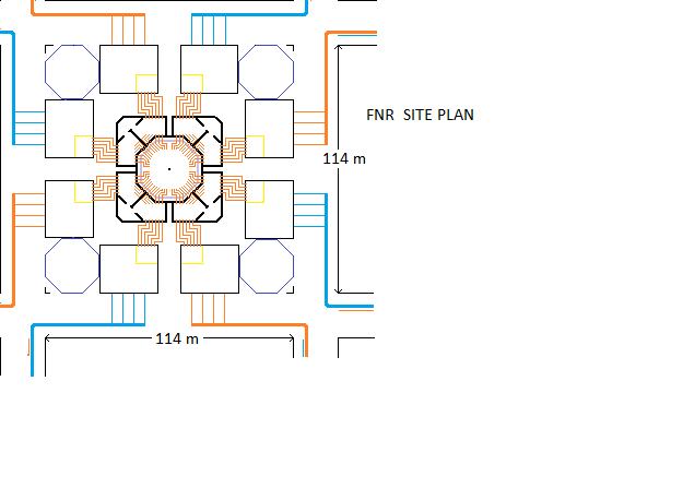 FNR Site Plan
The 700 MWt of low grade heat is delivered to four district heating pipe loops. Each district heating loop has 4 X 24 inch diameter buried pipes entering the FNR Power Plant site from a common 48 inch diameter pipe and 4 X 24 inch diameter pipes leaving the FNR Power Plant Site via a common 48 inch diameter pipe. Heat that is not used in district heating system is dissipated via 16 geographically distributed cooling towers, four of which are located at the corners of the FNR Power Plant site.
The use of 48 identical independent NaK heat transfer circuits enables equipment repair and maintenance while continuing to provide uninterrupted supply of electricity and heat. This feature has been shown to be important in other sodium cooled nuclear power plants where, due to use of larger common equipment components and due to the 15 hour half life of Na-24, even a minor intermediate heat exchange tube leak or steam generator tube leak resulted in a prolonged system shutdown.
HEAT TRANSPORT OVERVIEW:
In this liquid sodium cooled Fast Neutron Reactor (FNR) for safety purposes the systems that transport heat out of the sodium pool use a low pressure isolated NaK circuit to feed the steam generator. There is an induction type NaK circulation pump in the NaK return pipe from the steam generator.
The liquid level in the NaK dump tanks is controlled via the argon pressure over the NaK dump tanks. This gauge pressure varies from zero when the dump tanks are full to ~ 0.2 MPa when the NaK dump tanks are almost empty.
The normal NaK pressure is maintained by gravitational head and vacuum cover over each NaK loop. The NaK level is maintained by pumping argon from the top of the system to the NaK dump tank, or vice versa.
HEAT TRANSPORT LOOP ISOLATION:
There are 48 identical independent heat transport circuits, 6 associated with each of the 8 heat exchange galleries located around the perimeter of the sodium pool. Failure of any individual heat transport circuit does not cause a failure of the other heat transport circuits. Likewise, in principle, the NPP can be operated at part power using only a fraction of its 8 steam transport loops.
Each intermediate heat exchange bundle supplies hot NaK to a dedicated steam generator. Each NaK loop has three ___ parallel connected dedicated NaK dump tanks, a dedicated electric NaK induction pump, a dedicated vacuum tank and dedicated pressure relief vents. Any NaK or steam heat transport loop can be shut down for service while the other heat transport loops remain in operation.
Each of the eight heat exchange galleries has six associated NaK heat transport loops. Each NaK heat transport loop has a full load capacity to transport:
1000 MWt / (6 X 8) heat transport circuits = 20.833 MWt.
Each NaK heat transport loop is used by the turbogenerator to provide:
20.833 MWt X 0.300 = 6.25 MWe
of electricity. Thus the maximum possible FNR electricity output is limited by the NaK heat transport loops to about:
48 X 6.25 MWe = 300 MWe
Each NaK heat transport loop uses 16 inch outside diameter (OD) schedule 40S stainless steel pipe. This pipe has a wall thickness of 0.375 inch and a linear weight of
49.56 lb / ft.__________
NaK FLOW VELOCITY:
The cross sectional area of a 16 inch OD pipe is:
Pi [(7.625 inch)^2] = 182.625 inch^2
= 0.11784 m^2
Heat capacity of NaK = 982 J /kg-deg C
Density of NaK = 855 kg / m^3
(cross sectional area)(velocity)(density)(heat capacity)(120 deg C)= 20.833 MWt
(veloity) = 20.833 X 10^6 Wt / [(0.11784 m^2)(855 kg / m^3)(982 J / kg-deg C)(120 deg C)
= 1.754 m / s
STEAM PIPE REQUIREMENTS?
The intermediate heat exchange bundle has an overaqll height of almost 11 m.
Thus an equipment transfer airlock needs an inside length of at least 11.0 m.
At full load the NaK differential temperature drop across each the intermediate heat exchange bundle is about:
440 C - 320 C = 120 degrees C.
From 10% load to 100% load this differential temperature remains nearly constant.
The thermal conductivities of the Na and NaK are relatively high, so the intermediate heat exchange bundle NaK discharge temperature closely follows the Na surface temperature, limited only by the thermal conductivity of the intermediate heat exchange bundle tubes.
At full load the NaK flow through the steam generator tubes is turbulent, which enhances heat transfer. The thermal stresses in the steam generator are complex. The low end NaK temperature is pinned by the water temperature at the bottom of the steam generator which is a function of the steam pressure setpoint. Along the steam generator tubes the tube temperature above the steam generator water level is set by the internal NaK temperature whereas below the water level the steam generator tube temperature is closer to the liquid water temperature at the bottom of the steam generator.
SYSTEM COOL DOWN:
For rapid heat removal the steam bypass valve from the steam generator to the turbogenerator condenser is opened. Then water in the steam generator evaporates at 100 degrees C and cools the NaK and hence the Na down to about 120 degrees C.
THERMAL STRESS:
In the steam generator the NaK flow may be laminar, so there is a significant temperature drop between the NaK loop and the water/steam. This temperature difference will cause significant compressive stress in linear steam generator tubes. It will be necessary to use bent tubes and/or an alloy with a suitable TCE for the steam genertor shell to compensate for this issue.
Thermal stress calculations are very important but are beyond the scope of this web page.
Note that this thermal stress matter is more complex than it appears on the surface. In a conventional fire tube boiler the tube walls largely operate at the temperature of the surrounding liquid water, not at the contained hot gas temperature. Since the water temperature also sets the shell temperature this issue provides a high degree of stress relief that will not occur in a liquid to liquid heat exchanger such as the cooler portion of the steam generator. In a liquid to liquid heat exchanger another thermal stress relief method, such as bent tubes, may be required. The tubes will operate at the NaK temperature. There will be a significant temperature drop across the steam boundary layer.
HEAT TRANSPORT AWAY FROM THE NUCLEAR ISLAND:
The steam acts as a thermal fluid that transports heat from each heat exchange gallery, under the adjacent laneway, to a turbine hall which contains the corresponding turbo-generators, steam bypass valves, condensers and condensate injection pumps. The high pressure condensate return pipes come back under the laneway to the heat exchange gallery. The steam pipes should monotonically slope to corresponding condensate tanks that are located at the pipe low points in the turbine hall. The condensate tanks must be at a lower elevation than the turbo-generator to enable gravity drainage of water from the heat exchange gallery.
The two NaK steam generator manifolds are vented to the vacuum tank and then the atmosphere via 16 inch diameter ____vents with top ball checks which are sufficiently tall to allow for the change in fluid level due to the circulation pump pressure differential.
When the argon gas pressure over the NaK dump tanks is released, all the NaK will drain into the respective dump tanks.
TUBE FAILURES:
In the event of an intermediate heat exchange bundle tube failure the higher pressure Na will enter the NaK loop where it will cause loop radioactivity.
COOLING FOR MAINTENANCE:
When it is necessary to cool the sodium below about 280 degrees C for service or other purposes, heat can only be removed from the NaK using water cooling rather than electricity generation.
The steam generator PRV is opened allowing the pressure in the steam generator to fall to atmospheric pressure. Then evaporation of water in the steam generator will extract heat from the NaK and hence the sodium pool. The steam generator water level control system will automatically add additional water as the water in the steam generator evaporates.
PINHOLES:
Comment by Harry V. Winsor
Essentially, pinholes are partly an tube alloy composition problem, partly a fabrication QC problem, and partly a use environment problem.
Comment by: Charles Rhodes
There is a practical angle to the heat exchange bundle pinhole problem. Consider an automotive radiator. It may be designed to transfer 200 kWt of heat. Now consider a 1 GWt nuclear reactor. If it has only one stage of isolation it needs the equivalent of:
1 GWt / (200 kWt / radiator) = 5000 automotive radiators
If there are 2 stages of isolation that becomes 10,000 radiators.
Typical automotive radiators leak after about 20 years, Hence a power reactor heat exchanger made to the same standards can expect
10,000 radiators X 1 failure / 20 radiator-year = 500 failures / year.
Even with the best quality control techniques it is difficult to get that number under 50 failures / year. Hence it is really important to design the facility so that individual heat exchange bundle pinhole leaks can be tolerated, identified, fixed, replaced or bypassed without a reactor shutdown.
LWRs have a hidden advantage that they can tolerate a few pinholes because the fluids on both sides of the heat exchangers are primarily water.
Harry V. Winsor Comments
Na is a "free-electron metal" (ditto the other alkali metals): Structural metals must have partially-covalent bonds (beyond the free electron metals crystal structures) to prevent dissolution in them. This should allow the lattices to resist Na attack, e.g., as shown in Na-( FCC or BCC) metals. The problem comes when impurities (aka alloying elements) must be introduced for reducing structural metal grain sizes to prevent pileup of dislocations that can nucleate cracks or soluble inclusions. Thus, a first heat exchanger may need to be a Reactor-Na--Intermediate-NaK heat exchanger (minimum solubility of Na in the metal as shown by its phase diagram with Na). This should allow the best long term performance close to the reactor, since the exchanger materials can be selected to be the best at resisting Na-Attack from both sides in both Na environments. This heat exchanger could be operated to minimize pressure stresses that might allow migration of impurities in the exchanger metal chosen.
This means that the next heat exchanger is at the reactor electrical potential (probably grounded) on one side, and it needs to separate dissimilar fluid flows to be compatible with the high temperature needed for best generation efficiency. This likely increases its size (transfer area) and allows for a thicker metal separation between flows. It also allows for replacing heat exchangers if a pinhole does develop beyond operating tolerances. Since steam generation is needed for existing turbo-generation units, it is necessary to add another intermediate stage, which will lower the temperature, affecting the thermodynamic efficiency.
The water-side of this second heat exchanger would probably need to be coated with a second metal with higher water or corrosion resistance, and the chemical nature of the (nearly pure) water would need to be maintained at optimum for resisting water attack and frequent pressure cycling. This might include sacrificial anodes and other water-to-metal potential controls.
Comments by:John Rudesill:
Heat exchanger leaks almost always occur in or adjacent to welds. The metallurgy of the metal is disturbed and generally is not the same as the bulk material and corrodes faster. These local differences promote galvanic activity. I submit that the design needs to factor in the total length of weldments in each proposed heat exchanger configuration. Multiplying by the width of each weldment will give a total weld disrupted area and adding a thickness factor will give a volume of disrupted metal that can be related to the total metal mass. The more weldment volume in the total exchanger complement the higher the probability of
Thank you both for your theoretical comments relating to heat exchanger construction. Let me add another not so theoretical comment and that is thermal stress. These heat exchangers are all of the single pass counter current type with a large temperature differential between the input and discharge of each pass.
FLUID SUMMARY:
The various fluids are:
Na @ 100 C to 500 C @ 0. 1 MPa argon(atmospheric)
NaK @ 20 C to 490 C @ less than 0.1 MPa (vapor pressure)BR>
In normal operation the Na pool top surface temperature is 460 C and the steam generator bottom water temperature is 310 C. Thus the NaK discharge temperature from the steam generator is of the order of 320 C.
RELIABILITY:
The general approach is to use a large number of identical heat transport systems operating in parallel so that the system capacity factor consequences of taking a few heat transport systems out of service for repair and maintenance are minimal.
We must do all necessary to prevent products of corrosion accumulating in the Na and NaK.
Normally only the Na is radioactive. If an intermediate heat exchange bundle leaks that NaK loop will become slightly radioactive and that intermediate heat exchange bundle is taken out of service until the next reactor shutdown, The steam generator heat exchange bundles can be repaired or replaced while continuing to generate electricity.
Each NaK loop heat exchange bundle is rated at 21 MWt.
HEAT EXCHANGER LAYOUT:
In the heat exchange galleries the equipment relating to each of the independent heat transport loops is laid out in radial rows with a row center to row center spacing of 1.85 m at R = 18.5 m.
The minimum gallery inside length required for this equipment layout is:
5 (1.5 m) + 2 (1.25 m) = 7.5 m + 2.5 m = 10.0 m
In the heat exchange galleries the internal width allowance is 8.0 m.
BLACKSTART:
Bootstrap Warmup Procedure:
1) Use electricity or a natural gas boiler to heat pressurized water and hence the NaK;
2) Use the NaK to melt the sodium;
3) Use reactor heat to gradually raise the Na and NaK temperatures to 320 C;
4) Raise Na temperature to 460 C which raises the NaK temperature to 450 C;
5) Engage the turbogenerators;
6) Synchronize to grid.
RECOVERY FROM SERVICE:
Assume that the sodium pool temperature is initially above 120 degrees C.
Assume that initially the NaK is all in the dump tanks.
The first step is to apply argon pressure over the NaK dump tank to fill the NaK loop.
Then turn on the NaK induction pump. The NaK temperature should rise to the sodium pool temperature.
Raise the sodium temperature by movable fuel bundle insertion up to about 300 degrees C. The NaK temperature will rise causing the steam generator water temperature to rise.
Enable the steam generator condensate injection pump. The water level in the steam generator should rise to its set point. This water will form steam at a rate determined by the NaK flow rate.
Raise the sodium pool temperature to 460 C. The presssure in the steam generator will rise to about 10 MPa at which point the steam PRV should open releasing steam to the turbine.
While producing steam at low power set the turbine slightly below 1800 RPM. As the generator output voltage reaches phase synchronization, close the contactor.
Now gradually increase the NaK flow rate through the intermediate heat exchange bundle to increase the electricity generator output.
During black start only one heat transport circuit is started at a time to minimize the auxiliary power required for water electric heating and induction pump operation during black start.
Once the turbine is operating electricity can be generated and the system no longer requires auxiliary power for continuation of further black start steps. Thus there must be enough auxilliary power to fully turn on at least one generator.
STEAM GENERATOR TUBE FAILURE:
A steam generator tube failure will cause injection of steam / water into the NaK. The water will immediately form steam which will expand blowing some NaK into the vacuum tank and ultimately to the atmosphere. A sudden pressure or level rise in the vacuum tank indicates a steam generator tube failure.
MAINTENANCE:
There should be no radioactivity in the heat exchange galleries, which allows safe service work or NaK fire suppression in selected heat exchange galleries without causing a total reactor shutdown.
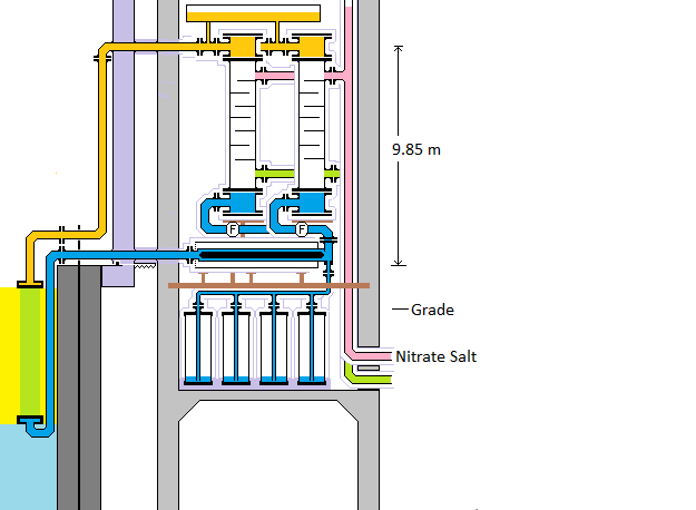
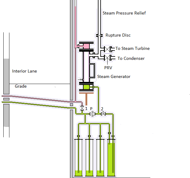
DIAGRAM:
A diagram showing an end view of a heat exchange gallery. Each gallery has 6 heat transport loops, one behind the other.
The left hand side of this diagram shows the intermediate heat exchange bundle and the NaK pipes. This diagram shows the steam pipes on the right hand side and the three parallel connected NaK dump tanks in the lower left middle. The vertical induction pump, the NaK flow meter and the vertical steam generators are in the middle of the diagram. Above the steam generator from left to right are the NaK vacuum tank and vacuum tank's pressure relief vent.
Note the dedicated steel I beam equipment supports.
Note that steam generator staggering enables a steam generator shell diameter of 1.2 m (~ 48 inches) and a steam generator flange diameter of 1.8 m (72 inches). Note that the steam generator centerline to end wall clearance is 1.25 m which is barely sufficient for the steam generator end manifold flanges + insulation.
The FNR site plan shows the 2.0 m wide space between adjacent heat exchange galleries that is dedicated to the airlocks that are required for moving fuel bundles and intermediate heat exchange bundles from their truck load/unload points into or out of the sodium pool space.
HEAT EXCHANGE GALLERY LOWER LEVELS:
Each heat exchange gallery has a lower level where the NaK dump tanks are located. Personnel access to the various heat exchange gallery levels is via a stairwell at the heat exchange gallery end farthest from the adjacent airlock.
The electric disconnects for the NaK induction pumps are wall mounted adjacent to the induction pumps.
Equipment in the heat exchange galleries is installed and removed from above using a mobile crane. The roof panels over the heat exchange galleries must be easily removable and replaceable.
There must be a large air vents in heat exchange galleries for outside air cooling.
An important issue in the heat exchange gallery is isolation of potential NaK drips. A likely source of these drips are the NaK pipe flange connections. Drip pans should be provided to collect dripped NaK. In the drip pans it will oxidize to Na2O and K2O. Any ambient water vapor will convert the collected material to NaOH and KOH.
In the basement under each heat exchange gallery is an isolated space that is used for an argon bladder. This space is air flow connected to the service access space under the pool deck. Any water penetrating this space from the outside must flow along the floor and into the FNR bottom drain located about 18 m below grade.
INDUCTION PUMP:
Induction pumps are used to circulate the NaK. The induction pumps must be sized to overcome the flow induced pressure head in the NaK loops. Note that these pumps should be located in the lower temperature NaK return pipes to ensure both cool operation and sufficient positive suction head.
An induction pump operates by inducing a circular current about a magnetic torpedo in the liquid NaK. This current crosses a radial magnetic field component and hence produces an axial force. External 3 phase coils, analogous to the stator coils of a 3 phase AC motor, create a suitable time varying magnetic field.
In normal full load operation the pumped cool NaK temperature is about ~ 330 degrees C and the induction pumps are oil cooled to protect the teflon electrical insulation from heat damage.
However, under circumstances when the steam generator is uncooled either natural or pumped circulation of the NaK can potentially cause the NaK temperature at the induction pump to rise to about 430 degrees C. Under these circumstances the induction pump can easily be damaged if there is insufficient pumped oil cooling. To prevent wide temperature excursions the NaK induction pump should be stopped if the corresponding steam generator contains no water.
The induction pumps have 18.000 inch OD schedule 40S (0.375 inch wall) 316 SS flow pipes and 16.00 inch OD schedule 40S (0.375 inch wall) 316 SS inlet and discharge pipes. The 18.000 inch OD flow pipe runing through the induction pump is partially obstructed by the induction pump's internal magnetic flux torpedo which has a 14 inch OD.
Induction pump details are set out at FNR Induction Pump.
GASKET CONSTRAINT:
A major constraint on the FNR design is gasket material properties. This FNR operates at too high a (temperature X pressure) product for use of elastomeric gaskets. Precision machined flanges and nickel coated copper gaskets are used. Inside the sodium pool space the flanges are located in an argon atmosphere. Suitable gaskets do not tolerate pipe misalignment, manifold distortion or high pressures. Hence gasketed mechanical joints need near optical precision fabrication. All the NaK heat exchanger manifolds bottom and top halves as well as the pipe mechanical joints are either fully welded or sealed with such gaskets.The flange bolts must have a smaller TCE than the flange material to prevent bolt loosening at high temperatures.
PIPE AND SODIUM POOL THERMAL EXPANSION:
The NaK-salt heat exchangers are in fixed positions with respect to the concrete structure. The intermediate heat exchange bundles move due to connecting pipe thermal expansion and contraction. Also the sodium pool inside wall moves due to thermal expansion. When the system is cold the outside of the cooler intermediate heat exchange bundle NaK inlet pipes should be almost touching the sodium pool inside wall. When the system is hot there is about a 0.2 m gap between this pipe outside and the sodium pool inside wall.
WELDING:
The manifold welds must be deep penetration equal in quality to the welds used on high pressure natural gas distribution pipelines. X-ray inspection and possibly a helium leak detector should be used for confirming weld quality.
This web page last updated January 17, 2026.
| Home | Energy Physics | Nuclear Power | Electricity | Climate Change | Lighting Control | Contacts | Links |
|---|